I wasn't quite sure how this switch worked but I suspected it has some sort of resistor where the more resistance that was applied the longer the delay would be. Only one way to find out though and that is to crack open the wiper stalk and see what goes on in there.
When I did this I found this unit. Its about the size of a 20 cent piece.
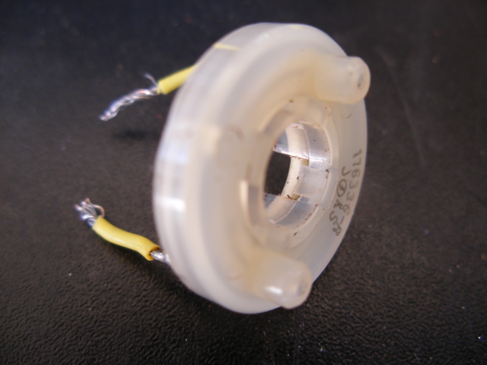
I opened it up to see what went on inside.

Basically it two halves with contacts that slide over each other to different positions as you rotate the switch. There are 3 intermittent settings.
Now that I knew what was going on I tested resistance to see what the readings were at the 3 different positions. It turns out in position 1 there is no resistance, in position the reading was 20k and in position 3 it was 40k. So in effect 20k increments.
The switch I am going to use has 4 positions so I will upgrade the intermittent functionality and have 4 settings. So as you can see in the picture below I have the switch and 3 different resistors, 20k, 40k and 60k and as per the original the other setting will have no resitance.

Here's a shot of what the switch will look like in the car. I will use this same style for all the accessories like wipers, hazards, headlights etc.

So all I need to do now to get this intermittent switch working is solder the relevant resistor on to the terminals.........

Then cover the exposed wire with some heatshrink (a plastic tube that shrinks on when heat is applied)

Then hit it with some heat from a paintstripper gun

Until it looks like this

Once all the wires and resistors were in place I tested it with the wipers and it worked a treat!

To be honest I am not 100% sure how the different voltages from that switch actually end up in intermittent pauses but here's what I think happens.
By selecting intermittent with the main switch, the wipers take their power from the little black box you can see here on the circuit board.

This black box I think is some kind of thermal switch that takes a certain amount of current to heat it up. When it gets to the right temperature it triggers and briefly turns the power on and the wipers start.
Then when you select a different speed on the intermittent switch the black box gets less power (owing to the resistors I showed you earlier) and as a result the thermal switch takes longer to heat up and takes longer to come on. There you have it a longer delay, before the wipers turn on momentarily again.
That's nearly all there is to it.
I say nearly as there is one more bit I need to tell you about and that is the self parking function that makes the wipers park at the bottom of the screen each time they are turned off. If you didn't have this....as soon as you turned the wipers off they would stop immediately, no matter what position they were in.
This is very important to the intermittent setting too. As I just said that thermal switch momentarily triggers and starts the wipers but it pretty much turns straight off again, so if it wasn't for the park circuit taking over, on the intermittent setting your wipers would move an inch or so then stop and after a few seconds move another in and so on.
The park circuit though ensures that after getting that little pulse to start that the wipers will then carry on going until they get back to the bottom of the screen. So how does that all work then?
The park function is all driven by a switch inside the wiper motor and is also contributed to by the way the wiring is done, so I'll need to drag out some of the earlier photo's I have shown you.
In this next picture inside the wiper motor you will recall we were looking at the worm drive and how it turns the white disk to drive the wipers. That white disk also engages with the nylon looking disk on the right. You can see that has four brass tabs sting through it. These hold a circular contact in place in the other side of the disk which has a power supply to it and it keeps ensuring the wiper motor gets power until it gets to the desired "park" position.

But you may well ask if the wipers are turned off how does the motor keep getting power? That all has to do with the circuit board. Remember when I was adding those wires so I could run the rotary switch to select off, int, slow, fast.....

.....did you wonder why it was necessary to have wires on the contacts in the off position (the terminals over to the left in the above picture) if the wipers are off, why do you need a circuit supplying power? Well now you know why, the off switch isn't on the switch you operate at all. In effect when you turn your wipers off you are actually turning on the park circuit.....the wiper motor actually turns the wipers off once the wipers reach the park position.....so you are not as in control as you thought you were!!!!
That's pretty much it, I will also add a momentary on switch that you press and let go to activate the windscreen washers but the wiring is done. I can now pack it all up in a little control box that will be hidden away in the centre console. All the driver will see is 3 switches the off, int, slow fast switch, the intermittent speed selector switch and the washer switch.
Now I will move on to the wiper mechanicals as there are a few slight mod's I need to make there too. I'll cover that in the next blog.
.
No comments:
Post a Comment