The truth is I don't. It's a case of asking lots of questions, learning as you go and dare I say it finding out the hard way. It also requires you to just start. Start anywhere and you'll find as you think about that, you can't do that bit until you finish something else....and to do that you need to start on another thing. Before you know it you have a heap of things on the go and they all start to come together.
The driveshaft is a classic case in point. It started with the steering column believe it or not. Ok, how the hell do you go from a steering column to a driveshaft????
- I wanted to look at where I might want to run the steering shaft as it affects what I will be doing with the exhaust.
- In order to know where I want the steering column though, I need to understand the seating position (incidentally this will also help to decide where to mount the gear shifter and the brake pedal).
- To know where I can have the seat I need to know where in the cabin I will sit, as I have to mount a fuel tank behind the seats and this will have the aircon unit mounted on top of it. Obviously the seats need to be forward of that.
- So where the fuel tank sits will become quite key to this.
- The fuel tank will need to be mounted on a chassis cross member that I need to add.
- I am hoping that the cross member can be multi-purpose and also be used to mount the rear stabiliser bar and exhaust pipe hanger brackets
- But most importantly I need to know where it can be placed so as not to interfere with the driveshaft.
- And there we have it, I need to know where the driveshaft will run and what it will be like. Will it be 2 piece and require a hanger bearing or will it be one piece.
- Lastly I have heard a rumour that you now need a safety hoop for the drive shaft rear universal, so that if the rear universal joint fails, the driveshaft can't fall out onto the road and harpoon a following driver.
Once the driveshaft is sorted I will start to work my way back to that steering column.
Another question I get asked is "when will it be finished?" As you can tell from the above, I honestly have no idea.
I also get asked "is it harder to build something from new or from scratch, or is it harder to restore old stuff?" I have to say I do like dealing with new stuff that just bolts on, but the reality is nothing ever really does. In fact when dealing with all new, you are invariably using and modifying old parts to fit. It is better in so far as you aren't rehashing someone else's mess and you don't have all the old grease and oil to deal with, but the trade off is a lot of time is wasted on not only building something that has never existed before in this exact specification, but also having to carry out your own research and development before you can even start building it.
The building of the driveshaft demonstrates this pretty well. Let's just assume for a minute I was restoring an old Camaro....
- Unbolt drive shaft
- Take to driveshaft guy to pull apart (or do it yourself)
- Clean up parts and paint them
- Take driveshaft back to guy to reassemble with new joints and balance
- Bolt back into car
In comparison this is the story of the driveshaft for the Coupe....
As you know I have a Jag rear.
At the other end I have a Lexus V8 and the factory Trans. The Lexus uses a two piece driveshaft and a large rubber donut that supposedly takes out some of the jarring between shifts and acceleration/deceleration. This front half of the driveshaft is rigid and runs constantly in line with the trans. Take a look at the diagram below. The transmission is on the left. The first part of the Lexus driveshaft (front propshaft) is directly in line with the transmission and it stays like that at all times as it is held at the other end by the "centre support".

Where it is labelled transmission output, that's where the large shock absorbing rubber donut is installed on the Lexus set up. Here is a picture of one.

And here is one installed.

Back to the diagram, you can see that after the centre support (sometimes called the hanger bearing) there is the rear propshaft that takes the drive back to the differential.
I don't want to set mine up like this mostly for ease, but also for aesthetic reasons. To do it like this I would need an additional cross member in the chassis to hold the centre support, I'd also need driveshaft safety hoops around every universal joint which would mean even more ugly cross members.

Instead though, what I will do is create a driveshaft that has a universal joint at each end as there are angles between the trans and the diff that I need to work with. These angles are deliberately there to ensure the universals flex and move. If you don't have these angles the universal joints constantly run in one position and they wear out and seize up.
You can see from this next diagram the set up I am going for.

A much simpler set up, but there is a bit more to it yet. You see a drive shaft universal mounts to a drive flange that looks like this.

But the Lexus one I have that uses the rubber donut, looks like this. So how do I make my three pronged flange (bottom pic) into the round one with 4 studs (as per the pic above)?

Let the fun begin. It went something like this......
- Visit my mate Pete Farrant at Auckland Balance and Driveshaft Ltd and ask about the best way to make a three pronged drive into a round flange.
- Pete advises there is a conversion you can get and he rings Damian at A1 Turbo (who does these Lexus V8 conversions) to find out what it is I need.
- Damian advises to go to Toyotaz Galore and ask for a Toyota Hilux drive flange as they are interchangeable as most of the Hilux ones are quite similar. Take the old 3 pronged one in for comparison.
- I visit Toyotaz Galore and ask for a Hilux drive flange.....the conversation went like this
- What year?
- Don't know, but it needs to replace this 3 pronged one?
- What's that off?
- Lexus V8 trans
- What year?
- 1994
- We don't have any of those.
- That's ok I need one off a Hilux to do a conversion
- What year?
- I don't know, I just need to ensure it is the same fit as this and I gather they are all quite similar across the Toyota range. If we could just have a look at one and count the splines (this is a 23 spline) and measure the machined diameter, I am hoping we can match something up.
- No I need to know what year or what part number. You could try Active 4x4 in Onehunga
- I wasn't going to get anywhere here it seems.
- I drive to Active 4x4 in Onehunga. 30 mins away and only to find they don't open on a Saturday
- I give up and decide I will do a bit more research. I find the trans most commonly used on a Hilux is a G52 and these are in a LN106 or LN130 Hilux.
- I go back to Toyotaz Galore the following week with this info.
- Sorry, we don't have any and even if we did we would want to sell you the whole gearbox. Suggest you try Dodson's wreckers.
- I call on Dodson's.
- Sorry, don't know we'd have to have a look, leave your number.
- I get a phone call later. Sorry, we don't have any.
- On my way home I pass Motortech 4x4 so dropped in there on the off chance.
- No sorry, don't have anything like that. Why don't you try Toyota, their prices are surprisingly reasonable for genuine parts and they will have full catalogues on what is available. Even if you have to get it ex Japan its only 3 days.
- Next day I try Toyota.
- Can you supply a Toyota Hilux drive flange that will fit a Lexus V8 Auto?
- What's it off?
- Lexus V8
- What year?
- 1994
- They don't have a drive flange.
- I know that's why I need to get a Hilux one. Can we have a look at the Hilux listings and see if there is a flange that will fit the Lexus V8. I am told its been done before and it's a straight swap.
- Oh yeah look here's one!
- Cool, do you have one so we can compare?
- No I need to order it, but that's ok I can do that it will be here tomorrow.
- I call back to Toyota next day and the part has arrived, but its 27 spline not 23. Bugger!
- Hmm we're a bit stuck now.
- You don't have a part number?
- No. Is there any way you can check to find out the specs of the parts. Is there any way we can look up all the drive flanges and find out which ones have 23 splines for example.
- No.
- One of the other guys overhears the conversation. There's a few things we can do leave it with us.
- Next day I get a call. We have a solution for you.
- I call back into Toyota and they have sourced an adapter. Awesome, it will work. Not what I was after, but it will solve the problem.
This is it after I had it polished and HPC Ceramic coated.

These bushes press into the larger holes.

Here they are pressed into place.
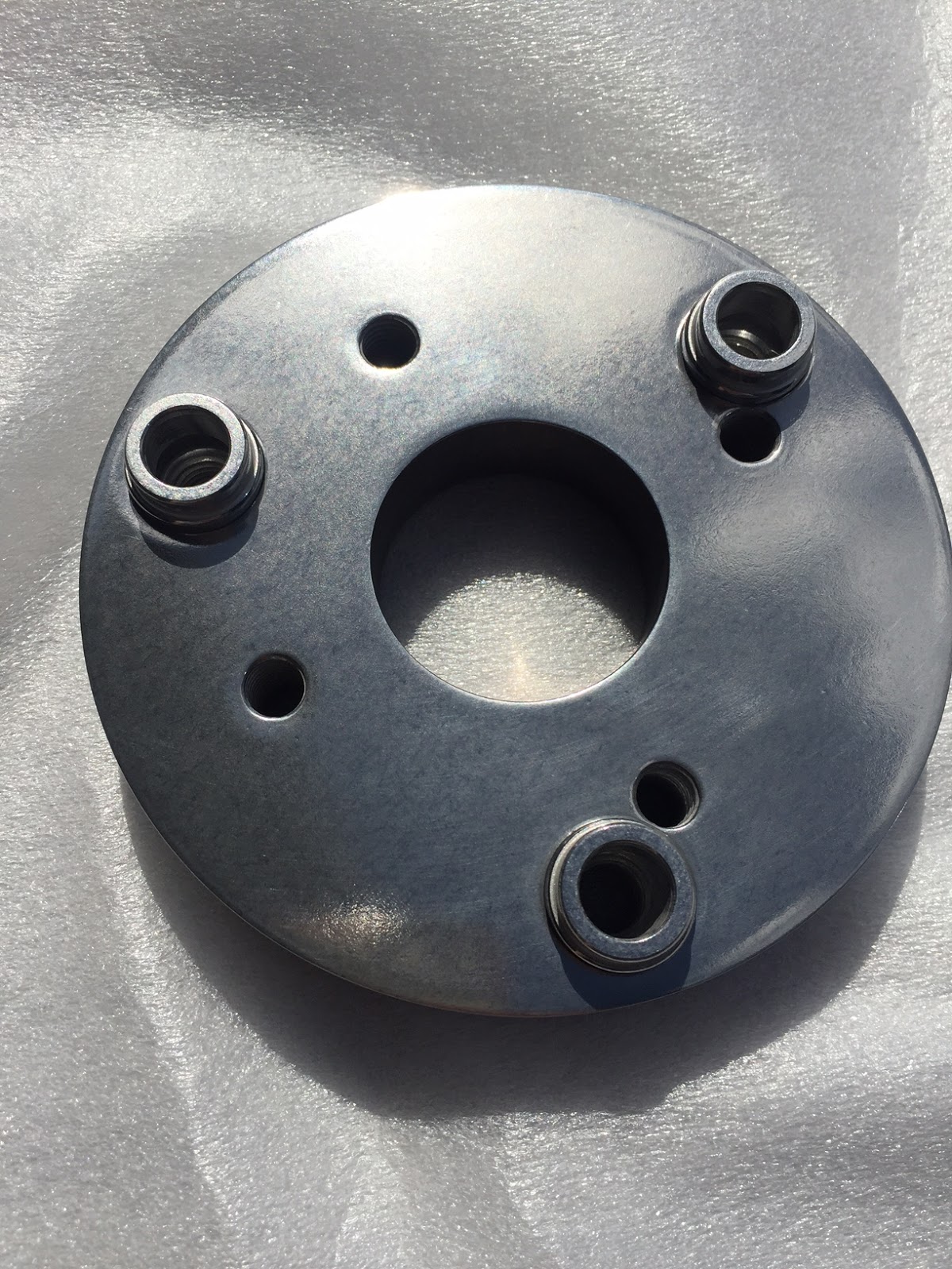
Now the three pronged drive flange I have bolts on. Of course that has also been HPC coated too.

On the other side you can see the 4 smaller holes that the driveshaft universal will bolt to. Nice workaraound.

So now it's back to Pete to find out how to measure up for the driveshaft itself. It has to be a really accurate measurement as the engine and trans are fixed and the diff on the Jag rear is fixed (independent suspension), so the driveshaft has to fit exactly in between.
Apparently it's not that simple though, as even if you could get the measurement millimetre perfect, you'd never be able to install the driveshaft, as you need about 20mm of movement to install it. Pete suggested I get a Hilux driveshaft as they have a slip joint in the shaft that does not require the two piece driveshaft and hanger bearing I mentioned earlier.
They look like this assembled. You can see one end is a smaller diameter. That piece actually goes inside the larger diameter on a spline.

Here is one disassembled. You can see the splines and how the hollow piece would fit over that splined shaft. What this means is the tube part can slide in and out over the splined shaft while still remaining engaged. This will give me about 10 inches of fore and aft movement. Remember I probably only need about 20mm. All good!

I'm not going to go into it, but I had a very similar experience as above when I tried to source the Hilux Driveshaft - What part number? What year? GIVE ME STRENGTH!!!
Anyway, I finally found a second hand Hilux drive shaft with a slip joint for the princely sum of $80. I now, hopefully have all the bits I need.


The adapter and universals having been polished, are now back from HPC. I will reinstall the drive flange, take a measurement between that and the diff drive flange, then get Pete to make and balance the driveshaft for me, using the hilux one I bought to raid that slip joint from.
Pete will source new universals and new tubing then balance it on sensitive and precision machinery to ensure it will run nice and smoothly once installed.
At last I am going forwards and not running around like a headless chicken....well at least until I need to find another non standard part.


