Total Pageviews

Wednesday, May 23, 2012

Engine - Engine Cover

You might remember, almost 2 years ago now, when I first bought the engine, that I was giving thought to how I might make an engine cover to hide the engine a bit. Not so much to make it look like something other than a Lexus V8 but more so to make it a bit more appealing.

Click on this link, it will take you back to that post. "Engine - Engine Cover Design"

When I came up with that design I was only doing it from pictures as the actual engine was down in Wellington with Phil who of course wired it all up and got it running for me.

As far as the design was concerned I wasn't really that happy with it as it was pretty much still like the original one smoothed off a bit and with a fancy paint job. Since then I have been able to look at the actual engine now that its home and come up with a few more ideas.

I didn't want to try and make the engine look like a Ford or a Chev....its not.....and I don't mind that it is a Lexus or if anyone knows that. I just want it to look a bit better finished and maybe a bit more refined.

A big part of being able to do this was shifting the inlet pipe to the rear of the engine, which I did about 6 months ago. Click here to see that post "Engine - Intake Manifold Modifications" This paved the way for me to be able to make a cover that fitted more snuggly to the engine and one that was symmetrical.

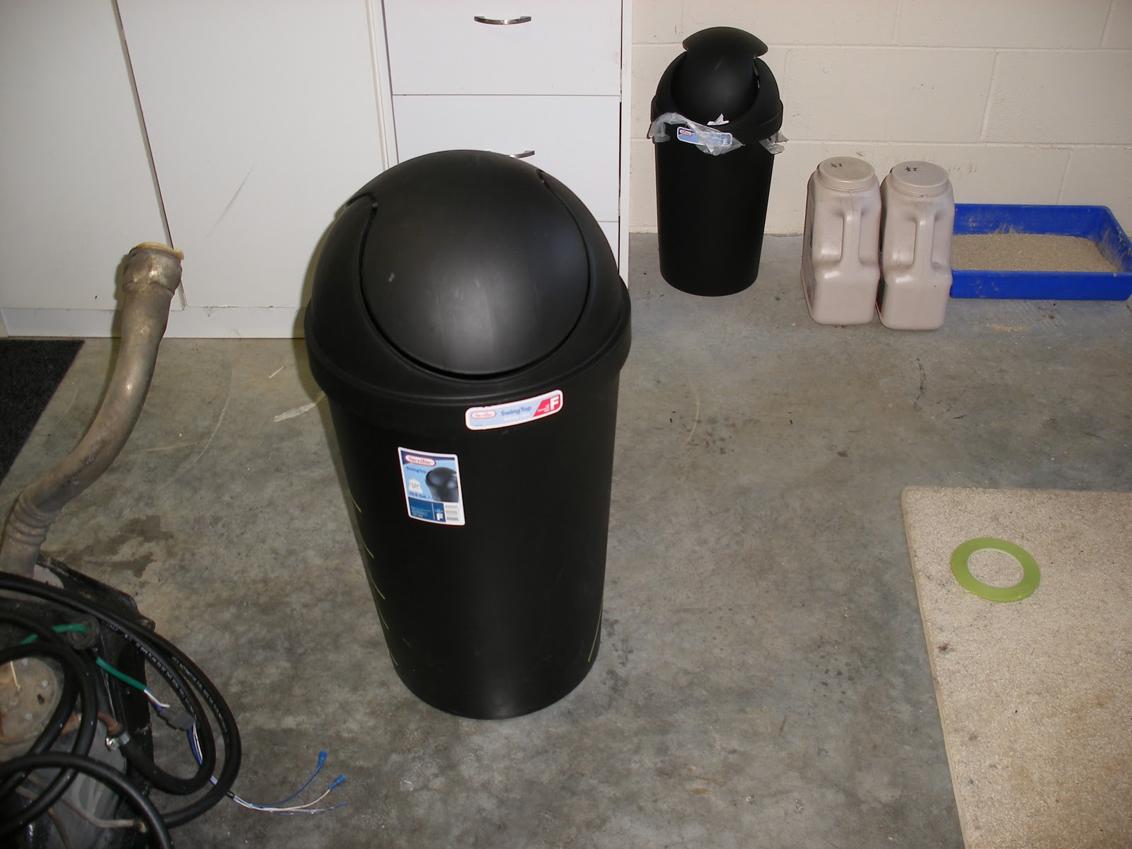
So......armed with a rubbish bin, two sheets of cardboard, some poster tubes, plenty of masking tape and some plastic tubing I decided to get what was in my head onto the engine.....with a few tweaks and modifications as I went.


I want to make the engine cover out of Fibreglass and ultimately it will be painted to match the car. This will allow the shiny bits to be shown off while hiding all the uglies underneath.

After looking around a bit I decided a rubbish bin would be the basis for my engine cover.  What was even better was the fact that it was a two for one deal at the Warehouse, so I even got a new rubbish bin for the shed too!


To get underway I lay the bin on its side and waited for night to come! 

Then I grabbed my new toy (its a set square that allows me to project a flat laser beam at various angles) and I turned the lights out and projected a line onto the bin. I then marked the line using pinstripe masking tape.


After marking one side I lay some perpendicular lines across the bin.


Then added a centre line.


From the centre line I was able to measure out the other side and mark it. Then I cut the shape out using a sharp knife.


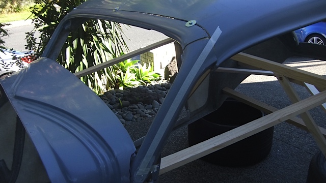
Here is the first part of the cover sitting on top of the engine.


That was fairly easy but the hard work was about to begin. This is where I had to hide all the ugly stuff you can see in the picture above, that lives between the black plastic cover I just made and the aluminium cam covers with the ribbed plastic strip running down the centre.

So here goes......first attempt. I thought what I would do was lay masking tape over the engine, and then fill over the top of that with papier mache.....yep thats right, just like we used to do at art class in school.

Here is the engine all masked up.


In this next pic you can see I have added some tubes. The idea of these is to make it look like they form part of the air intake. This has two purposes....the first is to take the plainness away as these will be polished stainless or chrome, so they add a bit of a feature.

Secondly though, the Lexus engine has some ugly big black boxes at the front of the engine and I want to hide them, so by having this inlet arrangement I can cover the black plastic cam boxes and make them look like they are part of the air intake too. You will get what I mean a bit later on.


Now after doing all that I decided I couldn't be bothered with all that papier mache and that I could do better with cardboard, so I taped a sheet into place on one side of the engine to see if I could get a better result. Here's what it looks like now.


And here is a side on view.


In this next pic you can see a pocket that I intend ducting those pipes into. If you double click on this picture to the right of that pocket you can see the big square black cam box. That will also be covered as I mentioned above and will hopefully look like it is part of the air intake.


From the front of the engine I needed to fabricate a panel to cover the ugly bits on top of the front of the engine. Here I have the cardboard in place and cut to go around the radiator hoses.


Here it is cut further and folded into place. The Mickey Mouse ear looking bits are the front of the covers that will hide those black plastic cam boxes.


And now, here it is all in place with the mocked up tubes in position.


Another view of the same thing.


And another look from the front. I am kinda happy with this, but still a long way to go.


So next up, I want to cover these plastic cam boxes.


This is where the cardboard tube came into play. Looks much tidier already.


Next up I completed the top of the engine by putting more cardboard in place and another piece of the cardboard tube over the cam box on the other side. 

Once I had done that the cover looked a bit plain so I created these "nostrils" to make it look a bit more functional. Then by adding the plastic cover I made from the rubbish bin earlier it is starting to look a bit better and certainly a lot different from original. 


Its amazing what 24 hours and a few minutes reviewing the previous nights work does. I decided the "nostrils" looked a bit crude, so I came up with a different plan. Firstly I took a section out of the cardboard tube a bit like I did with the rubbish bin above.


Here it is cut out.


Then I laid that on top of the engine cover as a pattern to draw around.


I then cut out that piece and turned the section of the cardboard tube over to turn it into a scoop. Here it is taped into position. I like this much better. The black tube sticking out of the vent hole will be removed later and I will fashion a grill that can be chromed/polished to fit in the opening.


Now that is done, I set about taping the plastic top cover into place. This covers all the throttle cables and linkages at the back of the engine.


Here's what it looks like from the front. 


So what is this funny shaped bit for?


Taped in place it flares out from the top cover to hide more of the ugly bits at the back of the engine.


Here is another view of the same piece.


I then fashioned a top panel to join that "wing" to the black plastic top cover.


What I also noticed while doing all this was that line the sides of the top black cover made, were pretty much in line with the small scoop I made earlier. You can see this if you look again at this picture below. Draw a line along the side of the black cover and it lines up with the side of the scoop.


So here it is again with those lines blended together. The two bits look like they belong together. Now we are cooking!


Okay so what was that plastic tubing for?


I am using it to give the edges some definition and depth. At a later point i will build up the surface above the tube and then the cover will have a nice round edge over the tube. You'll see more on this later, so don't worry if it doesn't make sense just yet.


Here is some more of the tubing taped in.


I also ran a length of the tube down the centre of the top cover. Again this will just add a feature that will make it look a bit more refined. Anyway this next picture is where I am up to. Really starting to take shape now. I'm still not happy with all aspects but I will develop it more as I go and I think it is at least on the right track.


Compare it to what it looked like originally....poles apart.

Sunday, May 6, 2012

Body - Gluing the roof back on

Well after many hours just sitting in the shed looking at the coupe from every conceivable angle, I am finally ready to join the chopped roof back onto the body. I am glad I did ponder like this for a while as I did end up taking another inch out of the back of the roof to get it to look right and I also have it pretty clear in my mind now how the windscreen frame and cowl will come together. Its important to just sit and assess or you can spend a lot of time redoing things or worse still find out too late that you should have changed something.

Anyway today was the day to start putting it back together.....so how do you join fibreglass that has been cut? Actually its pretty forgiving stuff. New fibreglass bonds to the old almost seamlessly, so any mistakes can easily be repaired.....but there is a right and a wrong way. I am no expert but I will try and explain.

When you cut and join two pieces and look at them in cross section they look a bit like this. The two pieces butt up to one another. Now if you glued the join....the bold black line.....it wouldn't last too long. It would definitely glue together okay with fibreglass resin, but with a car body in particular, they flex and twist and in no time at all your expensive paint job would be ruined with big cracks appearing.


You could put fibreglass resin and cloth on either side of the join. This would indeed be strong, but you can't have a big lump like that over all the joins.


So what would happen is you would sand the big lump down on the outside of the car to look like this. As you can see the outer patch has gone and while this joint is stronger than the first example it would still crack at the join in time.


So what you have to do is this. Firstly grind down into the join from one side like this.


Once that has been done fill the hollow with resin and fibreglass matting like this. 
 

Once that has hardened. You then hollow out from the other side.


And then you fill that hollow with resin and fibreglass matting as well. You then end up with a cross section that looks like this. Now that doesn't have a small join that will crack. Instead there is a much larger surface area for the new materials and the old fibreglass to hang on to one another.
 

 There you have it. That's what I need to do to all the cuts I made to the roof, the window frame and around the rear window. Here is the body outside all ready to go. As you can imagine all this grinding away of fibreglass is going to make a lot of dust.


Now for any of you who have worked with fibreglass like insulation for example, you'll know how prickly and itchy it can make your skin.......so I need to kit up for this lot. Here is a pic of me about to get underway.


And here I am in action with the grinder.


Once I had ground away the inside of the joins they looked like this.


After that it was a case of mixing up the resin and the hardener as I showed you in my earlier blog "Fibreglassing the Windscreen Frame" and layering that with fibreglass cloth. Initially I just added a couple of layers of fibreglass between the bolts that were still in place to hold all the pieces together. You can see below the fibreglass has been added (yes it is there despite the light shining through the join. The resin and matting almost go transparent. You can also see one of the bolts holding the two parts together.
 

Later on (next day actually) the two layers of fibreglass had gone hard enough and the joins were strong enough for me to take the bolts out. Once that was done I ground out the rest of the joins I couldn't get to before when the bolts were in place....and once again fibreglassed. Now that the entire join was clear I added several more layers to build up the join.


Below is what the joins look like now and without light shining in from the other side.


And here is what they look like from the outside.


I am actually pretty happy with the outcome and I am confident it will be strong enough and will look okay too once I ground out the outer joins and glassed them up again. Bring on another fine weekend next weekend.......oh but read on first there is some other bits I attended to while I had the tools and the materials at hand.

I decided I would have a crack at re-doing the the "A" pillars. They are the first pillars. The ones by the windscreen. Hence the name "A" as opposed to "B" pillars which are the second pillar behind the front doors on a car. And if its a 4 door car, the "C" pillar is behind the back doors.

So what did I have to do to the "A" pillars? Well they don't quite line up with the line of the roof. You can see here how the two angles just don't meet.


Here is a close up look. Ugly!


My mate Bill came round to give me a hand to lift the body outside and we got chatting about the issue I was looking at. He suggested I look at splitting the pillar down the middle and open up to see if the angles better matched then. I pondered on this and I could see that it might help, so that is what I did. You can see in this next pic I have a tape line running the length of the pillar where I was going to cut.


As I have shown you I need the top of the pillar to line up with roof, but I also need to look at the bottom of the pillar at the same time, to make sure that would line up too. 

The doors on the coupe will be pillarless, (there will be no frame around the glass) and the top of the door will line up with the bodyline directly above the swage line. The swage being the ribbed lined that runs along the side of the car.


You can see in this close up the bodyline that will line up with the top of the doors is 2 1/4 inches above the swage line. That is where I need the "A" pillar to end up to, so I transferred that measurement to the front of the door frame.


Here you can see I have cut the stump of the door frame down to 2 1/4 inches above the swage line to match.


I can now measure between the roof and the stump of the door frame to work out how long the pillar will need to be.


Here is the pillar and I am transferring the measurement onto it.
I have added a tape where I can now cut the pillar.


Here you can see the bottom of the pillar sitting on the stump of the door frame.


And here is what it looks like at the top. You can also see in this pic just how much the pillar needed to be opened up once it was split down the middle.


To overcome the difference between the roof line and the pillar I came up with an idea. I would take a "V" out of the pillar like this....


Then by making multiple cuts on the side.


And alternating cuts on the underside.
 

The pillar became flexible as you can see in the next two pics.
 

There you go, just like that.
 

I then did the same with the roof.


Now the two should line up. As you can see, they did. I taped all this in place from the outside so I could glass it in from the back. The idea being that the tape would act as a mould and that it would easily pull away once the fibreglass had hardened.


I had to use a clamp (thanks Roger) to help hold things in place.....then fibreglass, fibreglass and more fibreglass.


Here you can see what it looks like inside with the fibreglass now applied. Not the prettiest but it will work I think.


Here's a view from the front of the car.
 

And as if thats not enough.....that's it for this weekend. Next weekend if its fine I will attack the outside of those pillars and all those roof chop joins. Stay tuned!