Total Pageviews

Friday, March 11, 2011

Wipers - The rest of the wiring

Okay so we now have wipers that turn off and on. The last bit is to replace the intermittent speed selector with a standard rotary switch. Remember the current speed selector for intermittent is a ring that you turn halfway along the wiper stalk....and I'm doing away with the wiper stalk.

I wasn't quite sure how this switch worked but I suspected it has some sort of resistor where the more resistance that was applied the longer the delay would be. Only one way to find out though and that is to crack open the wiper stalk and see what goes on in there.

When I did this I found this unit. Its about the size of a 20 cent piece.


I opened it up to see what went on inside.


Basically it two halves with contacts that slide over each other to different positions as you rotate the switch. There are 3 intermittent settings.

Now that I knew what was going on I tested resistance to see what the readings were at the 3 different positions. It turns out in position 1 there is no resistance, in position the reading was 20k and in position 3 it was 40k. So in effect 20k increments.

The switch I am going to use has 4 positions so I will upgrade the intermittent functionality and have 4 settings. So as you can see in the picture below I have the switch and 3 different resistors, 20k, 40k and 60k and as per the original the other setting will have no resitance.


Here's a shot of what the switch will look like in the car. I will use this same style for all the accessories like wipers, hazards, headlights etc.


So all I need to do now to get this intermittent switch working is solder the relevant resistor on to the terminals.........


Then cover the exposed wire with some heatshrink (a plastic tube that shrinks on when heat is applied)


Then hit it with some heat from a paintstripper gun


Until it looks like this


Once all the wires and resistors were in place I tested it with the wipers and it worked a treat!


To be honest I am not 100% sure how the different voltages from that switch actually end up in intermittent pauses but here's what I think happens.

By selecting intermittent with the main switch, the wipers take their power from the little black box you can see here on the circuit board.


This black box I think is some kind of thermal switch that takes a certain amount of current to heat it up. When it gets to the right temperature it triggers and briefly turns the power on and the wipers start.

Then when you select a different speed on the intermittent switch the black box gets less power (owing to the resistors I showed you earlier) and as a result the thermal switch takes longer to heat up and takes longer to come on. There you have it a longer delay, before the wipers turn on momentarily again.

That's nearly all there is to it.

I say nearly as there is one more bit I need to tell you about and that is the self parking function that makes the wipers park at the bottom of the screen each time they are turned off. If you didn't have this....as soon as you turned the wipers off they would stop immediately, no matter what position they were in.

This is very important to the intermittent setting too. As I just said that thermal switch momentarily triggers and starts the wipers but it pretty much turns straight off again, so if it wasn't for the park circuit taking over, on the intermittent setting your wipers would move an inch or so then stop and after a few seconds move another in and so on.

The park circuit though ensures that after getting that little pulse to start that the wipers will then carry on going until they get back to the bottom of the screen. So how does that all work then?

The park function is all driven by a switch inside the wiper motor and is also contributed to by the way the wiring is done, so I'll need to drag out some of the earlier photo's I have shown you.

In this next picture inside the wiper motor you will recall we were looking at the worm drive and how it turns the white disk to drive the wipers. That white disk also engages with the nylon looking disk on the right. You can see that has four brass tabs sting through it. These hold a circular contact in place in the other side of the disk which has a power supply to it and it keeps ensuring the wiper motor gets power until it gets to the desired "park" position.


But you may well ask if the wipers are turned off how does the motor keep getting power? That all has to do with the circuit board. Remember when I was adding those wires so I could run the rotary switch to select off, int, slow, fast.....


.....did you wonder why it was necessary to have wires on the contacts in the off position (the terminals over to the left in the above picture) if the wipers are off, why do you need a circuit supplying power? Well now you know why, the off switch isn't on the switch you operate at all. In effect when you turn your wipers off you are actually turning on the park circuit.....the wiper motor actually turns the wipers off once the wipers reach the park position.....so you are not as in control as you thought you were!!!!

That's pretty much it, I will also add a momentary on switch that you press and let go to activate the windscreen washers but the wiring is done. I can now pack it all up in a little control box that will be hidden away in the centre console. All the driver will see is 3 switches the off, int, slow fast switch, the intermittent speed selector switch and the washer switch.

Now I will move on to the wiper mechanicals as there are a few slight mod's I need to make there too. I'll cover that in the next blog.


.

Thursday, March 10, 2011

Wipers - The wiring

Paul.....you're gonna love this one!!!!


Before I start on the switch side of things I need to get the wipers basically functioning from the components I had and in their standard "from the factory" form i.e. unmodified.

Again I harp back to all the work I did labeling wires and tracing circuits when I pulled the front loom apart to sort out the aircon wiring. This was invaluable once again with working out what went to where for the wipers, so I got them going without too much trouble.

Remember though I now needed to change the Toyota wiring over to the Holden Vectra Wiper unit. Different brands and one was Japanese design while the other was European design, so matching wire colours etc was not an option at all. Luckily though most systems work in a very similar way, so sorting out how five wires married up with another 5 wires wasn't too bad....going back to my statistics days at high school if you have five wires to join, there are 5 x 4 x 3 x 2 x 1 ways they can go together that's right, only 120 different ways you could connect them. OH NOOOOOO!


Actually no it wasn't that bad. The earth wire had a bolt through it so was obviously the earth.......so we are down to 4 x 3 x 2 x 1 combinations. Only 24!

Then by making a circuit from the earth to each of the other wires and touching it with ah a 12 volt power source I was quickly able to find slow speed and fast speed. So now I only have two wires to figure out. One would be a permanent power on wire and the other is a wire from the park position switch. It was a pretty quick inspection of the unit to decide which was which.

IMPORTANT NOTE. THE ONLY REASON I COULD EXPERIMENT LIKE THIS IS BECAUSE THE WIPER MOTOR WIRING IS HEAVY AND ONLY GOES TO A MOTOR WHICH AGAIN IS QUITE STURDY AND POWERFUL.....NO CIRCUIT BOARDS.....NO TRANSISTORS....NO RESISTORS.....NO CAPACITORS.....so I couldn't really do much harm. You WOULD NOT do this without being sure of what you were dealing with.


Ok with that out of the way, lets head inside the car now to look at the switches. Most cars these days have a wiper stalk on the steering column that will generally look like this.


This one is from........you guessed it.....a Toyota Celica!  It moves up and down to select intermittent, slow and fast. When you are on intermittent, you turn a ring halfway along to control the delay between sweeps 2.5 seconds, 5 seconds and 7.5 seconds. Lastly there is a button on the end to activate the washers and two sweeps of the wipers.

All this is controlled by the switching mechanism and circuit board that is hidden inside the steering column.

It is quite a complicated set up and I'm about to make it even more complicated by trying to retain all this functionality while converting it to a rotary switch with a knob so I can have it match with all the other switches I will be using. Also because I don't want an ugly stalk on the steering column. The plan is to have a panel in the centre console with all the switches in it and a door than can be closed when you are not driving.

As I said above I really want to keep all the functionality. Its not a requirement of the cert process, all you need for that is two speeds, but I have had my days of driving modified cars where if you wanted intermittent you had to turn the switch off and on manually. I also want self parking (where the wipers automatically stop at the bottom of the screen) as it is a pain in the proverbial having to hold your mouth right and count the sweeps of the wiper in a bid to try and time turning the wipers off when the arms are at the bottom of the screen.

So here goes my attempt at the conversion.....we'll look at the off, intermittent, slow, fast switch first of all....


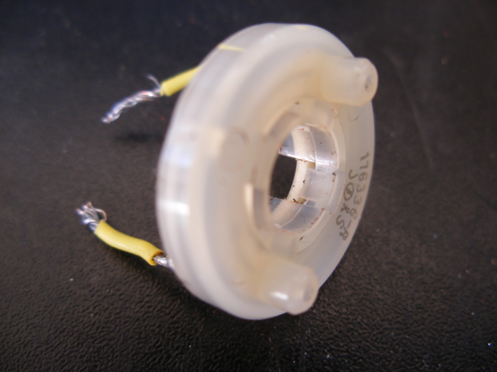
This is it here. The arm you pull down on, pivots in this housing and moves the two brassy looking contacts (at the top right hand side of the above picture) with four distinct clicks for off, intermittent, slow, fast. These contacts in turn make contact with terminals on the circuit board when the unit is assembled.


The pointer is showing you the two rows of terminals. The first row having 5 contacts and the second has just 3. There is a smear of grease in here to reduce wear and for smooth operation.

Now what I hoped to do was to use all this as is. I removed the wiper stalk so the unit now looked like this.....


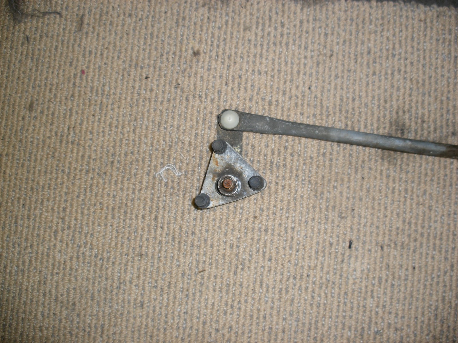
The screwdriver is in the hole where the stalk came from and I can now still make it work just by moving the screwdriver up and down. Remember though I want a rotary switch. So what I did was remove the arm inside the unit, the one that has those two brass contacts on it. Here is a close up of it.


I drilled a hole through the pivot point at the other end and cut a thread so I could screw in a bolt to use as a shaft. The idea is when you turn the shaft (imagine a knob on the end of it) the arm rotates to the 4 different positions to make contact with the terminals I showed you earlier.

Here is the shaft now in place.


It kind of worked okay when I put it all back together except with a wiper stalk you have a lot more leverage than you do with a knob that is at the actual pivot point. In essence it worked okay but was very stiff.

So what I did next was look at ways to make the switch "softer" to operate. Firstly there is the divisions inside the housing that hold the switch into the various positions off, int, slow, fast. They are the 3 peaked ribs you can see in the back of the housing in this next picture. The switch clicks into the gaps at either end and between the ribs i.e. 4 positions.


I could try and file or sand these down a bit, but that would be quite hard so I decided to look at the other part that clicks backwards and forwards over these ribs. This is actually located in that arm with the brass contacts and it consists of a nylon "nib" that is pushed outwards by a small spring. The nib then is forced against the 3 ribs shown above and of course it naturally wants to be in the gaps at either end or between the ribs, so it clicks into one of the 4 positions.


By reducing the pressure on this nib when it is going across the ribs, the switch will be softer to operate. I did two things to achieve that....I filed a bit off the nib, it wasn't enough, so I filed a bit more off....still not enough, so I then cut one coil off the spring. It was getting softer but still a bit tight. Another half coil off the spring and it was pretty good....trial time!

Regrettably, my plan, while it worked, wasn't quite as good as I would have liked. Firstly the shaft had to protrude out through the back of the switch as the unit screws onto the circuit board as I showed earlier and you cant drill through a circuit board without buggering up the circuits. What this meant is that the switch operated in an anti clockwise motion so where you'd expect to find off, the switch was actually set to fast and vice versa. That would just be bloody annoying.

In addition to that the switch was still very difficult to operate. The spacing between each setting was very small so it was easy to inadvertently go from off to fast when all you really wanted to do was go to intermittent. Again this would just be bloody annoying. A back to front switch with a hair trigger....that can only spell disaster! Back to the drawing board it seems.


My next option is to buy a switch and wire it to the circuit board so that the different positions of the switch mimic the two brass contacts sliding over the terminals. You see what those two brass contacts do is they each bridge across two terminals at a time.

On the top row the contact bridges terminal 1 & 2 in the off position, when its on intermittent it bridges terminal 2 & 3, slow = terminals 3 & 4 and fast = terminals 4 & 5.

Meanwhile the bottom row the contact bridges terminal 1 & 2 in the off position, when its on intermittent it bridges terminal 2 & 3, when its on slow it bridges 3 & a blank position (no circuit is made) and on fast it sits wholly on the blank position (no circuit is made)

So in a diagram you can see what I have mentioned above.


The black dots are the terminals. between them I have drawn brackets to show which terminals are connected in different positions. You can see the different settings labeled as well, off, int, low, high.

At the top of the picture I have keyed these to numbers 1, 2, 3, 4 in circles. Now what has to happen is I need a switch that has 4 positions obviously off, int, low, high but it is more complicated than that as it needs to make two circuits at once, just as the two brass contacts did on the original mechanism. When in the off position for example I have to connect the first and second terminals on the first row and at the same time connect the first and second terminals on the second row.

To do this you need what is known as a multi pole switch. And here is one shown. In the picture I am putting a circuit tester on to Pole A and Terminal 1.


The circuit tester has a setting that lets it emit a beep when a circuit is made. By doing this I can set the switch to each of the 4 positions and I can then test to see which terminals make a circuit in each one of those 4 positions. The diagram below shows the layout and markings for the terminals.


As you can see there are 12 terminals around the outside and three "poles" (hence multi pole switch) in the centre. When the switch is in the off position A makes a circuit with number 1, while B makes a circuit with number 5 and C with number 9. Then when I go to the next position with the switch the circuits all move round 1 position also, so A makes a circuit with number 2 now, B with 6 and C with10. They then all move round one more with the switch in the third position and again when I move the switch to the last position.

So what I decided to do was to put them into table form so I could easily see what was happening.


Here is my simple table. The positions of the switch 1 to 4 are listed down the left hand side. You then read across to see which terminals are making a circuit in that position i.e. in position 3 Pole A is making a circuit with terminal 3 so A-3, B has a circuit with 7 so B-7, then of course there is C-11.

Lets go back now to the terminal diagram.


It gets a bit tricky here as the terminals don't get used exclusively i.e. the second terminal in the top row for example is bridged with the first terminal when the switch is off but it is also bridged with terminal 3 when it is in the Intermittent position, so it used twice for different purposes.

The big thing I had to work out here was how to ensure I kept things separate so there was no circuit crossover (shorts). It took a bit of thinking but the numbers along the top and bottom of the terminals shows the combinations I eventually came up with.

I then cross checked this back to the table to make sure everything aligned.


The outlines drawn around the "letter/number combinations" represent the circuit being made. You might remember earlier I mentioned that the bottom row of terminals only made circuits in position
1 = off and 2 = intermittent. After that the contact moved off to a blank and didn't make a circuit any longer.

So looking at the picture above in position one I made a bridging circuit across the first two contacts in the top row using Pole A and terminal 1. At the same time I bridged the first two contacts in the bottom row using Pole C and terminal 9.

A-2 and C-10 were used in position 2 = intermittent.

Then in position 3 only the top row of terminals are bridged using B-7 = slow. Then lastly position 4 fast = B-8.

Okay in theory but what happened next?????????

Lots of soldering and checking and double checking with my diagrams and tables and here is the final result. An octopus of wires soldered to the back of the appropriate terminals......


.......and the other end of them soldered to the appropriate poles and terminals of the switch.


Now all I needed to do was hook the wiring up to the wiper motor and listen for any nasty fizzling and crackling sounds as things shorted and sparked......but no.......all was very silent.

Click the switch to intermittent......yes! Slow......yes! Fast......yes! It worked, my planning had paid off!


.

Wednesday, March 9, 2011

Wipers - How they work

There are a number of differing variations to wiper setups but the principal behind the way they work is fairly similar.

Initially I chose to use a set up from a Toyota Celica. Mostly because Garry Pegler still has the wrecks down the back of his place that I could raid and secondly because you will recall from the aircon I have the entire front section wiring loom. You will also remember that when I was trying to work out all the wiring for the aircon that I traced every one of those wires and labeled them......thank goodness......that hard work will all pay for itself now as I try and work out the wiper wiring.

Here is a picture of the set up.


This is the motor


 ....and these are the two drives. These are the bits that your wipers bolt on to.


The overall set up is quite long but its easy enough to shorten up as the sweep of the wipers is determined by the stroke of the motor and radius of the short arms that come off the back of the two drives shown above. So what that means is you can shorten the long connecting rods without any impact on the operation of the wipers, you just cut a chunk out of the middle to suit, then weld them back together again. But........its not quite that easy........

You see on the Celica, the wiper motor and drive is all mounted at the top of the firewall under the bonnet and are in full view when you open the bonnet. Now on hot rods, wiper motors and mechanisms are hidden. Looking at this unit I couldn't get it clear in my mind just how I could mount the motor behind the firewall and still get it all to work as the angle of the drive on the motor in relation to the arms was not going to suit. Sure I could have gotten there if I persevered but why make life hard for yourself.

Another trip to Pick a Part and I located this little beauty out of a Holden Vectra. Its an all in one unit that will still need to be modified but it will fit neatly up under the dash and out of view.


Whats more at just on 500mm (1/2 a metre) its really compact and shouldn't need much work done to resize.

So anyway just how do wipers work?

In effect you have an electric motor that spins over. It drives what is known as a worm drive (a kind of spiral) that interlocks with a wheel that has teeth on its edge. By doing that the motor that is spinning  a long shaft has its twisting action converted to the rotation of a large flat wheel.


In the picture above the motor is the black tube off to the right. When it runs it turns the screw like rod you can see at the bottom of the picture. Then (I should have cleaned it so you could see it) under all that gungy looking grease on the white wheel there is teeth that interlock with that shaft....so the shaft turns.....the worm drive spirals outwards......and that pushes on the teeth on the wheel which in turn goes round and round. With me so far?

What happens then is the plastic wheel has a shaft through its centre that has an arm attached to it.


The picture above is the other side of what we were looking at in the previous picture. The shaft that I mentioned was attached to the white plastic wheel can be seen protruding through the hole in the flat steel coloured mounting plate (roughly centre of the photo). Its a bit obscured by the arm in the foreground, but you can see it has a goldy coloured bracket coming off it.

Remember the white wheel is turning round and round so the shaft is doing the same........and of course the gold coloured bracket is also rotating.....a bit like the arm on a clock.

Now thinking about the wipers on your own car....they go backwards and forwards not round and round....thats where this conversion happens. You see the plastic looking black fitting that attaches to the gold bracket is over to the right when the gold bracket is at the 3 o'clock position but as it rotates to the 9 o'clock position it moves over to the left.....then as it returns to 3 o'clock is back over on the right.....we have now converted rotational movement to left, right, left, right. Away go the wipers! Easy as that!

Actually here's a video that demonstrates all that a bit better.


Well that's not quite all there is to it, I have just finished sorting out the wiring tonight to control the self parking, intermittent (4 speeds), the wipers (2 speeds) and the washers.

That will be in my next blog.


.

Monday, March 7, 2011

Wheels - Wheel mock ups

See if this influences your voting....

The two most voted for wheels so far are the "Spectrum" as below.....


......and the "Knoxville" as shown in the next photo.


Remember to have your vote over to the right hand side of this page!


.

Aircon - Its a wrap

You will recall last time I put up a post about the aircon the unit was pretty much complete and all back together again. The last job that needed doing though was to add some adapter plates to all the air outlets so I can later on direct the air to face vents, the footwell and to the windscreen.

This meant making up some templates that Tony Field kindly welded up for me. The three that look like vacuum cleaner attachments are the ducts that screw up under the dashboard to blow demister air up onto the windscreen. The remaining ones are those that Tony made. He made a really nice job of them and they fit perfectly.


Here they are all painted up and ready to install.


And now screwed into place on the aircon unit.


The blue hose is actually pool vacuum hose that is available from Para Rubber by the metre. I wasn't sure if it would stand up to the heat so I tested it first by blowing a paint stripper gun in one end of a length of the hose while I placed the kitchen thermometer (hope Janine's not reading this) at the other end. I set the gun on low heat and let it edge up to 90 degrees Celsius, that's about 195 degrees Fahrenheit Kevin :-)

The hose was soft but still kept its shape so I figure it will more than stand up to the task.

The demister vents are a smaller diameter so I had to buy some smaller hose for that and it thanfully screws inside the bigger hose so there was no trouble adapting between the two pipe sizes.


So that's it really until I get round to mounting the unit in the car and start plumbing all the gas lines and heater hoses.

So I guess that's what you'd call a "wrap".

.

Friday, March 4, 2011

General - We have a winner!

A while ago now I was reading the Hot Rod Forum and saw that a new "automotive community" known as RPMS had kicked off. It is basically a kind of buying group where you pay $45 per year to join and in return you get a membership card that gives you favourable discounts at a number of car related stores they have signed up to the scheme. The community covers hot rods, muscle cars, aussie cars, off roaders, imports, european cars and motorsport in general.

I know some of you might be a bit anti that, but I have to say I have an appreciation for most forms and while Jappa's don't spin my wheels I can see why the young guys are into them and they do some real nice work some of them too. I guess with Janine's son Carl being into Rotary's, my daughter Leisa being into Nissan's and her partner Kane who is big time into Honda's, I have to be a bit open minded......oh and did I mention I'm dropping a Lexus V8 into the Coupe?


Anyway I thought it sounded like a good idea so I joined up. They have a monthly prize draw and I won a 6 pack of V a few months back. Now I don't normally win anything so it was kinda cool to win the prize even though I don't drink V at all. I did manage to find an owner for them easy enough though.

Now since then I have been eying up the list of retailers I am potentially going to be able to do business with as I progress the coupe, so I have been thinking about RPMS quite a bit lately.

Anyway I was at the Hot Rod club the other night and had my phone on silent so I missed a call and there was a message. I had no idea who the call was from, but it turned out to be Nelson Beatson the Director of Sales and Management at RPMS ringing to tell me I had won a $3000 spending spree to be spent at any of the retailers they have association with.

Silvester V8Auto OneHytech EnginesAutolign - HPC - BOP PolishersCheers AutoFamous ShippingWestech AutomotiveA1 ExhaustMarshall PanelbeatersDynopowerBuddy ClubCustom AutoglassKiwi Race Cars TransgearNZEFICounties Auto PaintersPetes CustomsWired Auto ElectricalPauls AudioGary Capper PerformanceUpholsterers and TrimmersSteve Allan Auto RefinishersMcCullough Ltd - Central Soda BlastPerformance TransmissionGreenville PaintersClass A KustomsSinco CustomsFully EquippedKey West Fabrication & SuppliesHowat Engineering - Freelance AutomotiveRX7 HeavenParts ConnectionAction Canvas & UpholsteryTint A Car TaurangaAJay’s Ford V8 PartsHPE Motor ReconditioningBig Shed CustomsModified Vehicle Certification CentreMorrissey SpoilersTint-A-Car ManukauMF Motorsport FabricationsRivers Speed & SparesVTNZOil ChangersCoby Performance ExhaustPPS Paint Protection ServicesMag & Turbo

I can spend this at anytime over the next 12 months and can spend it all in one wack or at a number of different retailers over the 12 months.

At this stage I am thinking I will use it to buy the back wheels for the Coupe. The back wheels without tyres (because they are so big) are very expensive so I will still have to put a bit of money toward them, but it makes sense to me to get a big ticket item like that as it would normally take me an absolute age to get the money together. A nice item to have squared away and also really helpful when trying to set up the rest of the car.

I am probably going to go for something like these Boyd Coddington wheels in a 20 x 12

Legend - Knoxville


Cast - Ultimate 5


Cast -Smoothie 3

 Legacy F-22


Legacy Spectrum


Legend - Nitro

Legend - Double 5

I am happy to take votes on which wheels you think I should go for and also the finish. All the wheels are available in polished alloy or in chrome, but just so you can tell the difference, the first four are polished alloy and the last three are chrome.

At the top right hand side of the page you will see a survey where you can vote for the wheel and finish you prefer.

And last but not least........  
Thanks RPMS and thanks Nelson!
I am absolutely stoked!

Make sure you get in and get your membership everyone. You could be RPMS next big winner!


.