No brainer decision yeah, but the job at hand wasn't. I have burnt a few brain cells on wiring as you will recall from my blogs about the wiring for the aircon, and I am about to burn some more with the steering column.
The column is out of a Lexus and I have chosen it as it has a few of the high tech options I wanted. It has an electric telescoping action (you can bring the steering wheel closer to you when you are sitting in the car) and it has electronic tilt (you can raise or lower the height of the steering wheel when you are sitting in the car). In addition to that it has tilt away, which means when you turn the car off the steering wheel tilts up and out of the way to make it easier to get in and out of the car. Then when you turn the key back on the steering wheel goes back to where you had it. Pretty cool huh?
Another feature is that it has an auto position on the headlight stalk so that I can have a light sensing unit that will automatically activate the headlight circuit when it gets dark.
Oh and another thing it has the cruise control stalk as I will be hooking up the cruise control too.
All in all there are 36 wires I need to work with.
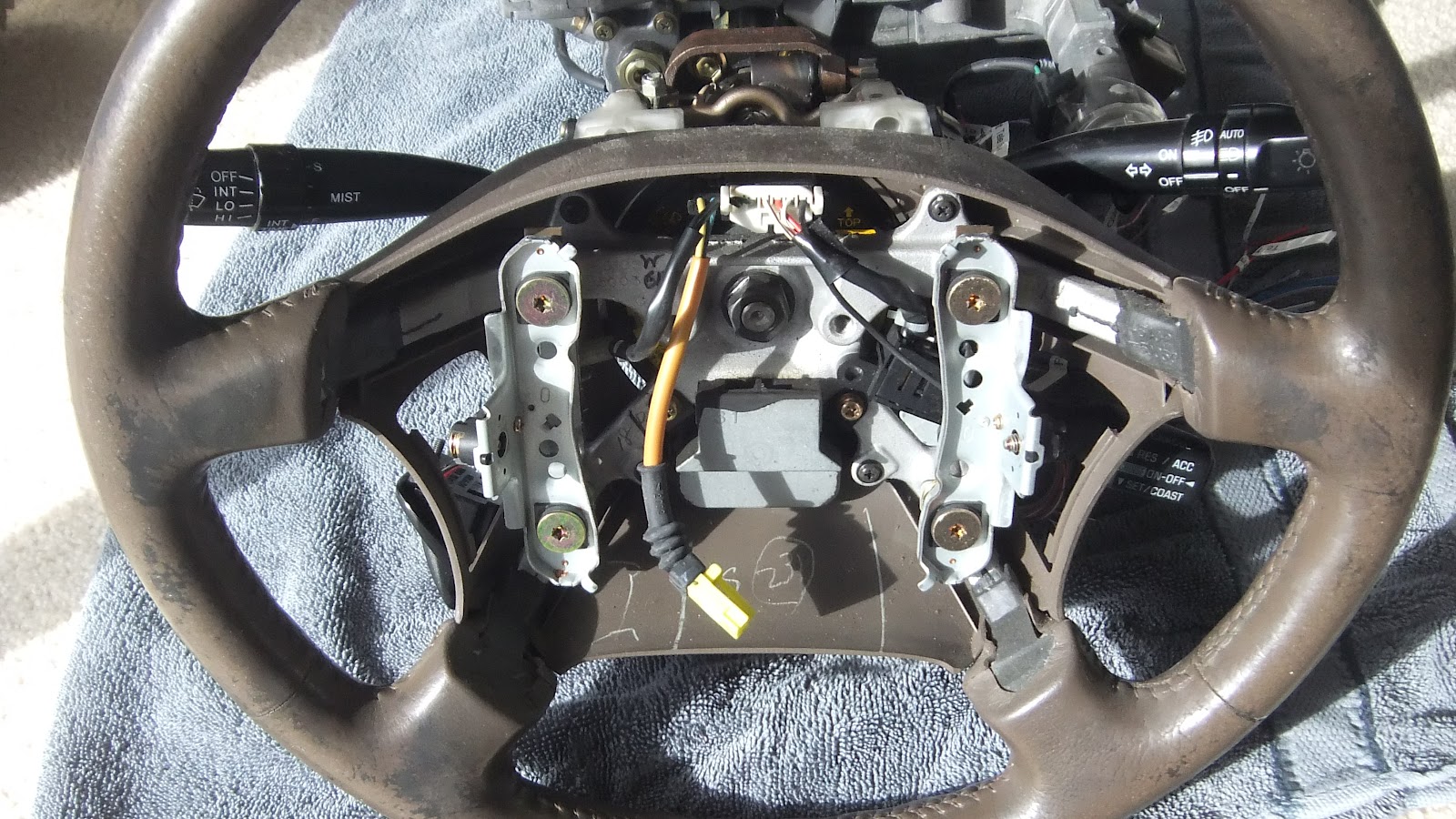
Here is a pic of the column. It is sitting on its end flat on the steering wheel.

This is another view now laying roughly as it would in the car.

Here you can see a close up of the Ignition key and mechanism. This will all go as it sticks out too much for one, but also I intend to run a push button start.

This is a small electric motor that drives the in and out telescoping motion.

This is the other motor that drives the up and down tilt motion. This tilt function has a position sensor that notes the position of the column before you turn the key off. This is stored in a small computer (yes there is a computer for the steering column) so that it can restore the column back to the same position once the ignition is turned on again.

This next pic shows the cruise control stalk. This is mounted to the steering wheel.....oh and in case you were getting concerned, no I won't be keeping this steering wheel, I have a billet aluminium one I will be using with a half leather wrap. I'll show you that another day, but rest assured it won't be this Toyota/Lexus one.

Here is another view from what would be the driving position. You can see the wiper and indicator/headlight stalks.
Now to help sort out the wiring Phil has given me a number of diagrams from which to try and sort out the circuitry.

As I have found before though, these don't seem to line up with what I have but they share some generic principals. The problem is these are way beyond my wiring experience. This is mostly because the Japs do things so much differently to the old style wiring I was brought up with. It isn't impossible to get your head around but for me at least I need someone to go through it with me so that I can get the gist of what is going on. Its just not so logical.....well at least not until I have it explained to me.
On this note I am forever thankful to Phil Bradshaw who is very knowledgeable about this and also because he has prepped all my engine wiring and incorporated a lot of the ancillary circuitry like lights, indicators etc using Toyota principals. So of course it makes sense to integrate into that which has already been created.
I did have a crack at trying to come up with a wiring diagram for the headlights much to Phils disgust. He has promised to come and smack me around the head and reset my wiring skills to Japanese when he is next in Auckland.

To give you an idea how different it is......my experience is this....
A wire goes from the battery to the light switch. When the switch is in the on position it makes a circuit that allows the power to go down another wire to the light bulb. The bulb is earthed to the chassis as is the battery and thus a complete circuit is made and your light goes.
Now this is the Japanese version of the same thing as provided by Phil.
12 volts from battery goes thru white wires to separate 10 amp fuses for left and right headlights. This is so if one fuse blows you still have the other headlight.
Wire from fuses changes to B and L respectively.
These wires end up in the headlight looms and need to be connected to the common terminal on each headlight bulb. Therefore the headlights always have power to them.
The headlights are turned on depending on what is earthed from the bulb. Dip beam is a white wire (for both left and right) and high beam is a red wire (again for both).
These red and white wires both go to the dip/main change over relay, with the dip wire (white) going to the normally closed terminal, the red wire to the normally open. Thus the default position is low beam.
When the dip switch (separate twin core wire with black over sheath) red wire (connected to your dip/main switch RL1 wire) is switched to ground it trips the relay to switch from low beam to high beam.
The main beam indicator lamp should also light up.
But - Note the lights won’t actually go as yet because the headlight relay(and hence the light bulbs) isn’t connected to ground.
Back to the hi/lo beam relay – the output of that relay is a wire that runs into the normally open terminal of the headlight relay.
This relay is closed when the Green ‘headlight relay trigger to ground’ is connected to the R wire in your headlight switch.
The park lights are also fed via a fuse and relay, with the relay triggered when the Brown ‘park light relay trigger to ground’ wire is connected to the GW park light wire on your light switch.
You won’t have headlights unless the park lights are turned on.
Or in other words
バッテリーから12ボルトは、左右のヘッドライトに10アンペアのヒューズを分離するためにスルー白い線を行く。これは、まだ他のヘッドライトを持つようであれば1ヒューズが切れます。
ヒューズの変更からBとLにそれぞれ配線してください。
これらのワイヤはヘッドライトの織機で終わると、各ヘッドライトの電球の共通端子に接続する必要があります。したがって、ヘッドライトは常に彼らに力を持っています。
ヘッドライトは電球から接地されているものに応じてオンになっています。ディップビームは白い線(左と右の両方)とハイビームでは赤線(再度の両方)です。
これらの赤と白の線が両方のディップ線(白)が正常に閉じられた端末は、通常、オープンに赤線に行くと、リレー上のディップ/主な変更点に移動します。したがって、デフォルトの位置はロービームです。
ディップスイッチ(シース上に黒を持つ別のツインコア線)赤線は(あなたのディップ/私は疑うメインスイッチRL1線に接続されている)、それが旅行のハイビームをロービームに切り替えるためのリレーをグランドに切り替えられたとき。
いくつかのマジックは私の配線内で発生し、メインビームのインジケータランプも点灯します。
しかし - ヘッドライトリレー(したがって、電球)をグランドに接続されていないため、ライトは実際にはまだ行くことはありません注意してください。
バックHI / LOビームリレー - そのリレーの出力は、ヘッドライトリレーのノーマルオープン端子に実行線です。
グリーン地面にヘッドライトリレーのトリガーが"あなたのヘッドライトスイッチでR線に接続されている場合、このリレーは閉じられます。
公園のライトは、ワイヤブラウン"地面に公園のライトリレーのトリガ'はあなたの光スイッチでGW公園光の線に接続されているときにトリガリレーと、ヒューズ、リレーを介して供給されます。
私はそれを正しく配線している場合は、公園のライトがオンになっていない限り、あなたはヘッドライトを持っていません。
Believe it or not Phils description does make sense to me now that I have traced the wires on the column and thought it through in conjunction with his notes, so thanks immensely Phil.
On that note I have committed to Phil to never again try and create a wiring schematic but that instead I will identify which wires are activated by different switch positions and then incorporate that with his explanation as to how that will fit with the wiring he has already prepared for me. One good thing Phil at least its all Toyota so far!!!
Anyway back to my part in all this. I have a circuit tester that is battery powered and is sometimes referred to as a multimeter. It has many uses which I won't go into here, but one of its functions allows it to be switched to give an audible tone when you have a circuit.
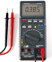
So what i can do is touch the black terminal (The black handle with the metal spike coming out of it) to a wire and put the headlight switch to the park light position for example. Then I use the other red terminal from the tester to touch other wires coming from the headlight switch. Once I find a wire that makes a circuit the meter beeps. Thats one circuit found.
You really need more than one pair of hands to be able to hold the two terminals and operate the switches at the same time. The cat is clearly interested. I wonder if I can get him to hold the terminals while I operate the switch.......

Samson.....Saaaamsoooon.....here pussy, pussy!
Now that's a lot of wires on a steering column...wow!
ReplyDeleteI'm no good with electrical stuff either but given enough time I'm sure you'll figure it out.
Yeah it requires a lot of patience and its also very helpful having a qualified engineer like Phil around. Hope your Coupe is going well now Kevin and that all the teething problems are out of the way.
ReplyDelete