Total Pageviews

Monday, November 21, 2011

Body - Goes into the Mould

A few weeks back I ordered the body from Koop de Glass. It is owned by Robin and Lynda Barnes and they run the operation from their home in Inglewood. A small town just out of New Plymouth. I asked Robin if he could make it and time it so that he could bring it up to a huge swapmeet and car show we have in Auckland in January called the Kumeu Classic Car and Hot Rod Festival.

The idea is Robin will be able to have it on display at the event all weekend and I will take it home afterwards. Robin thought that would work for them, so things got underway.

Here are the first pics of the progress. I am no expert on the process but I'll do my best to explain it to you.

What you see in this first picture is the mould. It is taken off an original car and is made in sections that bolt together. In the picture the mould is upside down (on its roof) and the big opening closest to you is the drivers door frame. To the left is the front (firewall) and to the right is the back (boot or trunk).

If you double click on the picture you will see a larger version and you might be able to pick up the bolts running along the top of the windscreen (remember its upside down) and a few other places if you look closely.

The shiny black finish is the surface that the fibreglass will be laid up onto. Before this happens though it is coated with a releasing agent so that the fibreglass body doesn't stick to the mould. You can also see a bit of grey towards the back.....that is the finished colour of my body being brushed on. It seems weird that it goes on first and that it is being brushed on, but what happens is that finish (gelcoat) is making contact with the the very smooth and shiny mould so it will come out looking smooth and shiny like that too. Any brush marks will be on the underside where the fibreglass will be layered.


Here's another angle. You are looking through from the engine bay towards the back of the car. The small shaped opening right in the middle of the picture is the back window.


Here the gelcoat has been applied to the entire mould.


Now that the gelcoat has been applied, the fibreglass starts to get laid. It is basically a cloth made of thousands of glass strands. Resin is then brushed onto the cloth and worked in with brushes and rollers so that it soaks the fibreglass cloth. 

The resin is a two part mix of resin with a hardener. The mix is quite critical. Not enough hardener and it won't set. Too much and it will go hard before you can work it into the mat properly and before you have a chance to use it at all. In extreme cases the reaction will happen so fast that heat builds up and it starts to fizzle pop and smoke.

The hole you can see the floor through is where they had a canvas roof insert in the original car. I will either close this up or I might even fit a sunroof.


This is looking out through the boot opening.


In these next pictures you can see a different colour mat has been applied. This is a very tightly bound mat that gives the body strength.


The furry edge in this next picture is where the fibreglass has been laid over the edge of the mould. This gives you a good idea of what the fibreglass matting looks like in its raw state. In fact if you look at the front edge of the door opening you can see a rectangular strip laying there.


That same furry edge has been trimmed in this next picture.


As you can see progress on the body is well underway. This fibreglass is layered again and again to build up the desired thickness, so Robin will keep doing this for a while yet. More pictures to follow I believe. 


In the meantime click on this link to see their website Koop de Glass. You will be able to see some of their other products and some cars that have been created from their products. Remember that white 33 Ford Coupe I had before selling it so I could fund this project? It came out of this very same mould!

Thanks Robin and Lynda for sending the pics through. Looking good!!

Thursday, November 17, 2011

Engine - Serpentine Belt Pulleys

On the Toyota V8 some of them used an Hydraulic pump to drive a cooling fan for the radiator. These are a fairly ugly set up so I was keen to do away with that. Instead I will use an electric fan.

This change meant getting rid of the hydraulic pump and thankfully Phil had a replacement pulley set up that bolts in where the pump used to be. You can see the new unit, its the rusty looking drive flange and the aluminium housing behind it.


One problem is that this pulley off the original hydraulic pump.....


.....isn't going to fit over the drive flange. You can see below the diference in the centres.


The other issue is that the new item doesn't line up with the other pulleys. Its hard to tell in the photo but the pulley at the left of the pic below is the new unit, and it doesn't line up with the next pulley.


So what I need to do here is construct a spacer.

Firstly I drew it out on paper and then I had to talk nicely to Bill Dobbin who kindly spun this up on his lathe.  It looks fantastic. Thanks Bill.


I also had to put longer studs on the pulley as they now needed to go through the flange, the spacer and the pulley.  You can see here the longer studs are in place.


In this next picture the alloy spacer is fitted.


And here it is with the pulley fitted as well. Thankfully it all lines up nicely!


The next step is to relocate the alternator as it had to be removed to make way for the steering rack. You can see right in the middel of this next picture (the thing with the two small pipes coming out of it) the steering rack. This is where the alternator used to live.


Right above that is the power steering pump. The silver can at the top of the photo is the reservoir for the power steering fluid and the pulley beneath it drives the power steering pump.


I will remove the power steering pump.....
Now you see it......


Now you don't......


Gone just like that. That means I now have a space I can relocate the Alternator to.
It will mean a few modifications to get the alternator to fit in its new home but once done it should fit within the body confines and work just fine.

So now I have two jobs on my hands. The fitting of the alternator oh and what about the power steering???? I have a trick lined up for that so keep watching for future blogs where I will cover both of these.


Sunday, November 13, 2011

Engine - Intake manifold modifications

I want to have the engine looking a bit more "Hot Rod" so one of the things I want to do is make the engine look a little more symmetrical.

This is what the engine looks like as it comes straight out of the Toyota donor car. I need to do away with that plastic engine cover and try an have a bit more of the engine exposed.


A few of the alloy parts will be polished and some parts painted the same colour as the car. This should give me the overall look I am after, but.......


You can see here the engine isn't very symmetrical with a large intake pipe coming in from the left of the picture. This is basically a big air tube and on the end of it there will ultimately be an air filter.


The piece to the far left in this next picture is the AFM or air flow meter. This tells the computer how much air is going into the engine. Then there is a black pipe that goes into large alloy piece. This alloy piece is called the throttle body. You can see a couple of cables coming off the the top of it at the very top of the picture. One of these is the throttle cable that goes down to the accelerator pedal and the other one goes to the cruise control module which tugs on this or releases it, to regulate the car to the set cruise control speed.


Here is the unit taken off the motor. The large plastic box beneath the tube is also part of it and is basically a reservoir I believe, so that if you stomp on the gas the engine can take a gulp of air.


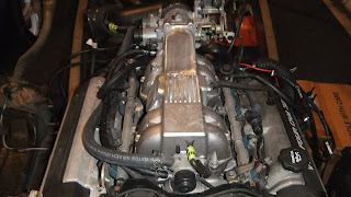
You can see here, how much tidier the engine is with the unit removed.


The plan now is to remount the intake at the rear of the engine. Here's what it will look like. 


Here's another view from the back of the engine.


And now looking down on top.


So now I need to remove the intake manifold and modify it. Actually not quite true, I bought another one so that if it is a failure, I still have the original one undisturbed.


So lets get into. First of all I hacked the mounting flange of the side of the manifold. 


Then hacked the top off the manifold.


After hollowing out the back of the manifold the flange now mates up to its new home.


I will now need to make up some fillets to join the flange and make it airtight to the top of the manifold.


 Here are all the components ready to go.


This is a plate that will block off the hole where the throttle body used to mount.


Here are all the inlet parts being held in place.


After Tony Field took to it with a pulse mig welder and a polisher as well.....it came out like this. Pretty pleased with that! Thanks Tony!


This next picture shows the new manifold sitting on top of the old one. I'll just bolt the new one on in place of the old one, then I can re-plumb all the vacuum lines, a water cooling line, then remount the throttle body and air flow meter. Then we can fire up again. 


A few weeks later I finally got round to doing all that and here it is....its quite hard to see so double click the images if you want a closer look.


As you can see from the front its now all looking nice and symmetrical.


Now that it is all plumbed up, what better excuse than this to try firing up the engine and see if it will run okay following the change. So after hooking up a few wires and fuel, I gave it go and it ran perfectly.....a bit noisy for the neighbours.....but perfect from where was standing!

Now the next step is to make an engine cover out of a rubbish bin. Yes thats right I will make my engine cover out of a rubbish bin!!!!